Noah Moroze
Experiments with the CM1K Neural Net Chip
Written on July 23rd, 2017 - 14 minute readThis is a reposting of a post originally published on Medium.
In March 2017 I received funding from the MIT Sandbox program to build a product using the CM1K neural network chip. The CM1K is an integrated circuit that implements RBF and KNN classifiers in hardware, which supposedly gives much better performance than implementing these algorithms in software. I proposed to use this chip as the basis for a breakout board that could interface with popular hobbyist electronics platforms (such as the Raspberry Pi or the Arduino). All code and schematics can be found on this project’s Github page.
Prior Work
I was inspired to begin this project after randomly searching Google to find out if a chip like the CM1K existed — I wanted to know if anyone had developed an ASIC that implemented machine learning algorithms in hardware. I stumbled upon the CM1K very quickly, but project examples were few and far between.
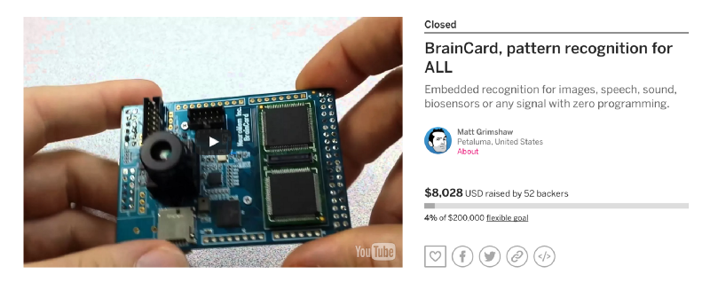
I did discover the Braincard, a failed Indiegogo campaign for a breakout board incorporating the CM1K. It was extremely similar to what I intended to develop, claiming to interface the CM1K with the Pi, Arduino, and Intel Edison. Despite its failure, I didn’t lose confidence in my idea — Braincard seemed to lack the documentation and visibility within the hobbyist community necessary to be successful, which doesn’t necessarily say anything bad about the CM1K itself.
 Sad reacts only :(
An interesting note is that the Braincard campaign is actually affiliated with Cognimem. After digging a bit, I discovered multiple companies that all appear to be affiliated: Cognimem, General Vision, and Neuromem, among others. They all appear to be tied together by the inventor of the technology in this chip — Guy Paillet. If you wanna go down the rabbit hole, take a look at his LinkedIn profile… In any case, my best guess is that the Braincard was an attempt by General Vision to grow demand for the CM1K among the hobbyist market.
I found even fewer examples of third parties using the CM1K. The few references I dug up were this simple breakout board and this research paper. Unfortunately, both of these sources lack any clear documentation demonstrating real-life application of the CM1K.
It was hard to find examples of the CM1K being put to the test. With Cognimem claiming “endless possibilities,” I was motivated to build a breakout board and evaluate the CM1K for myself.
Developing the Breakout Board
I initially planned to complete a couple versions of a breakout board in the spring. The first would be a fairly minimalistic breakout board consisting of:
- the CM1K itself
- a 3.3v and 1.2v regulator to power the chip
- a 27 MHz oscillator to provide a clock signal
- pull up resistors and filter caps where required
- a power LED
- headers to break out every single line on the IC
This board could then be hooked up to whatever platform I wanted, and once I developed software and was able to evaluate the best way to use the chip, I could design a second board with the extra bells and whistles needed to make it interface nicely with my platform of choice.
Due to time constraints, I never got close to working on this second design. In any case, it turned out there was little need for it in the experiments I was running: it was super simple to interface the first rev board with the Raspberry Pi over I2C.
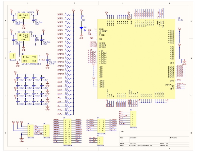 Schematic!
I began designing the breakout board in Altium. Drawing up the schematic was fairly straightforward, but the layout took me a while. I settled on trying to fit everything into 2 square inches, which didn’t give me much room to play with. I lined the headers around the edge of the board, and placed the IC in the center. I initially thought I could do the board in two layers, but after two attempts I couldn’t fully lay it out nicely. My biggest pain point was trying to cleanly distribute the 1.2v and 3.3v lines to all of the scattered power pins on the IC. After three redesign attempts, I settled on a four layer design, with the third layer being split into 1.2v and 3.3v power planes. The 1.2v plane was located directly under the IC, so all pins requiring a 1.2v input were routed backwards with a via going straight down to the 1.2v plane. The 3.3v power pins could then be routed forwards with vias going down to the plane. Since all the peripherals use 3.3v, this made it easy to provide 3.3v to the rest of the board.
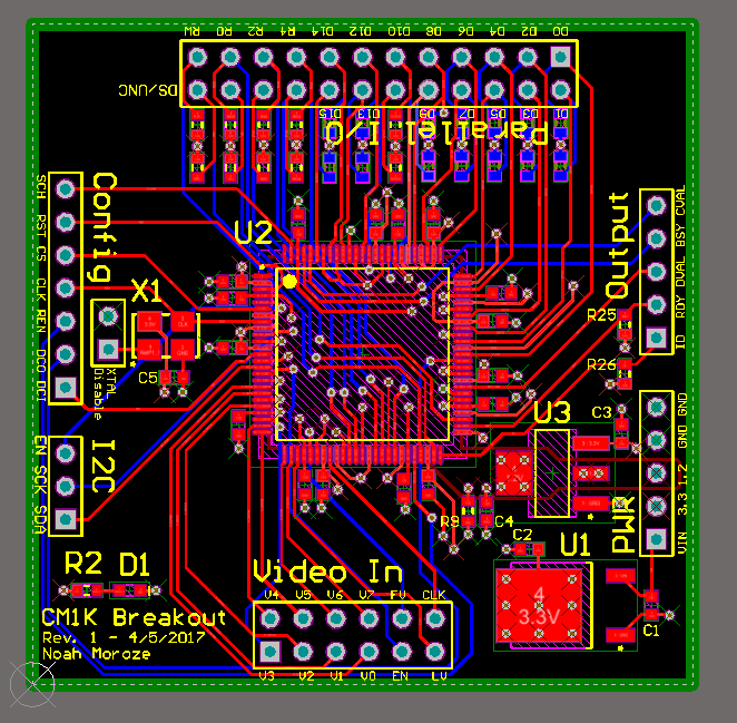 Routing complete!
After the board was designed, I needed to send it out for fab. The last time I had done this was a few years ago when I got something made at OSH Park for my high school robotics team. At this point, I needed the board much faster than a batching service could provide, so I ended up going with 4pcb.com, using the 66each deal to get two of my boards fabbed at $66 each. As a student I was able to have the minimum order quantity waived, which was pretty awesome.
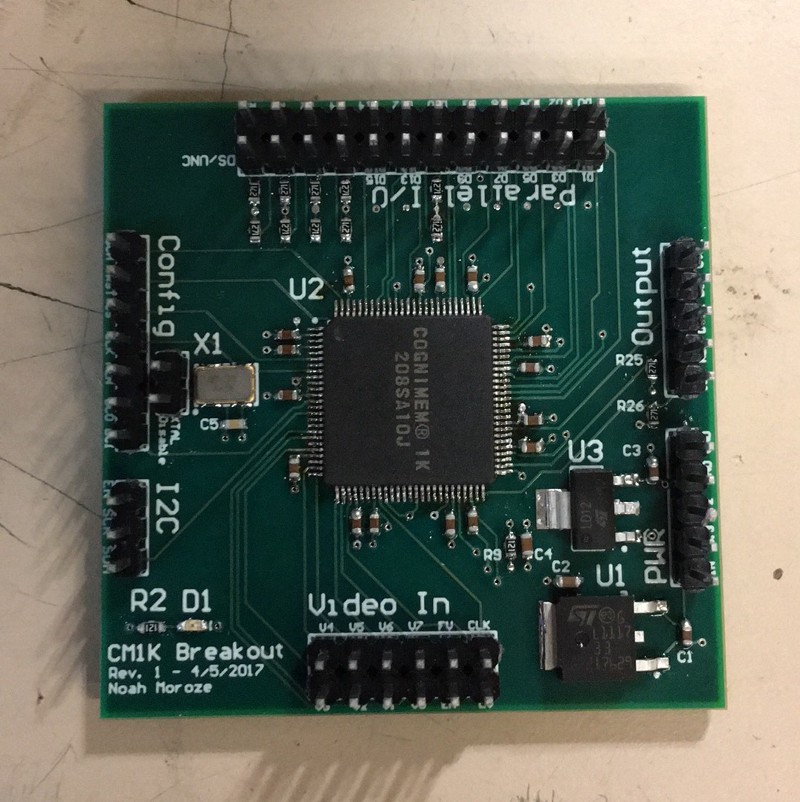
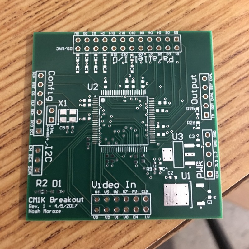 My breakout board straight from the fab in all its glory.
Once my board and all the components arrived, it was time for assembly. I brought it in to MITERS and got to work soldering everything up using a hot air gun. Every component went down super easily… except for the IC, which took a bit of work to get right. I began with that, and buzzed all the breakout pins to make sure it was tacked down right. After many iterations of buzzing and wicking and trying to carefully apply more solder, it seemed alright.
 All populated!
Once I finished soldering, I brought the board over to a power supply and plugged it in. The moment of truth passed uneventfully: the power light turned on and the board did not start smoking or heating up. Next up, I decided to try and use an oscilloscope for the first time to check the output of the oscillator. The output seemed to really suck at first, but after being unable to find a fault in my board, I realized I just didn’t have any clue how to set up the oscilloscope. After some Google searching and some calibrating, I got an output that at least matched the frequency I was going for (even if it wasn’t totally clean). Oh well, things seemed to work out fine anyways.
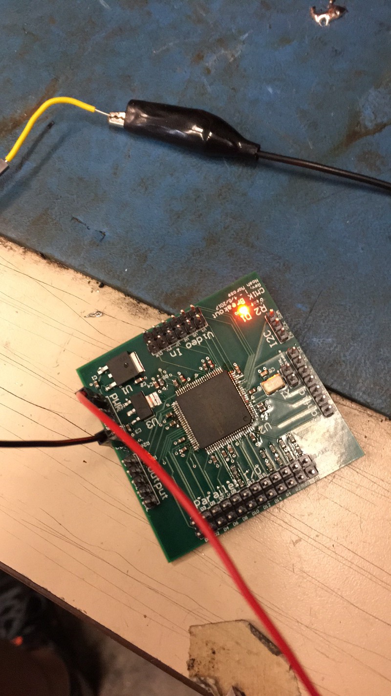 The moment of truth!
With this initial battery of tests completed, it was time to wire up the breakout board and get coding!
Developing the Software
I started off by hooking up the breakout board to a 3.3v Arduino Micro I had lying around, chosen because it was the only Arduino I had with a 3.3v logic level. The wiring was easy: I just hooked up the two I2C lines and tied a few configuration pins to GND as necessary to get I2C working. I then wrote a function that successfully read from the CM1K’s NCOUNT register. After generalizing that to a function that could read/write to any arbitrary register, I was able to validate that the CM1K’s hardware seemed to be working as specified in the datasheet.
Once the hardware was validated, I spoke to a friend of mine who suggested I try benchmarking the chip against the MNIST dataset. I decided this was a worthy goal, and set out to use the CM1K to implement KNN classification on MNIST.
I decided I didn’t want to have to worry about fitting the MNIST training data set onto my Arduino, so I picked up a Raspberry Pi Zero W along with some peripherals to make wiring easier. I wired it up just like I had with the Arduino, and got to work!
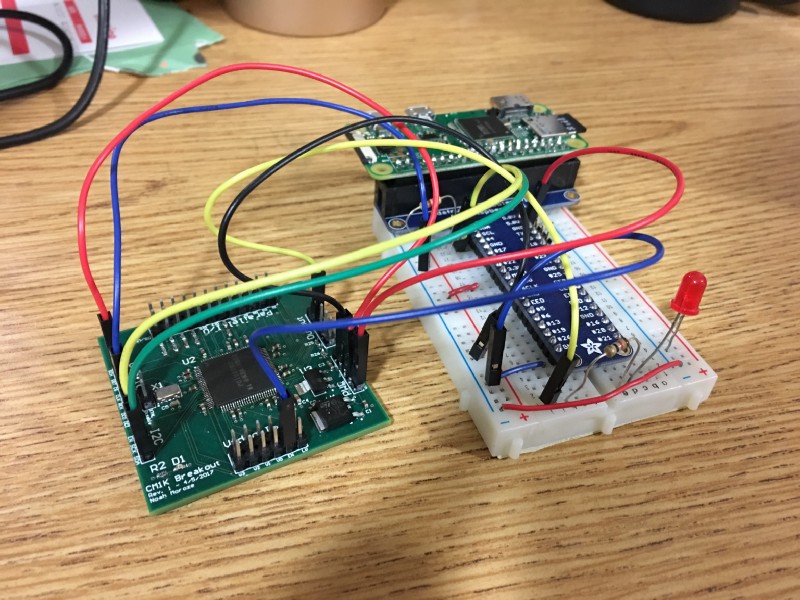 The Raspi Setup in all its glory.
I decided to write all my code in Python, using the smbus module to talk to the CM1K over I2C. I started off by writing a simple test script based on some pseudocode found in the CM1K Hardware Manual. The script uses a test register, TESTCAT, that writes the same value as the category of every single neuron. It then iterates over each neuron and checks to make sure that its stored category matches the value written to TESTCAT. This script worked, so I decided it was finally time for the dirty work.
The first step was to downsample the MNIST images. Each image is a tiny 28x28 pixel image to start with, but the CM1K stores data in each neuron as a length 256 vector storing byte values. Therefore, using a single byte to represent the color value of each pixel, I had to squeeze each image into 16x16 pixels so that I could fit one image into each vector. This was easy enough: I used python-mnist as a lazy way to get the training data, and then used Pillow and Numpy to resample the images. Along with downsampling to 16x16, my code also flattened each image into a single length 256 vector that could be fed to the CM1K.
Since a single CM1K can only fit 1,024 vectors, I wrote the code to choose a random 1,024 images from the training set to actually use. Given that the full training set uses a total of 60,000 images, I was worried that this would introduce a huge limitation in the performance of the chip.
The training procedure simply involved writing each of these images into the CM1K. I used the chip’s save-and-restore mode, which is supposed to speed up the process a bit by allowing you to write a vector directly into each neuron’s memory, without them adjusting their activation functions (which are relevant when the chip is running in RBF mode, but not KNN).
The test procedure then ran a configurable number of test images against the CM1K. I began by simply taking the closest neighbor (k=1), but got terrible results this way (unfortunately, I was doing Bad Science™ and didn’t record these results). However… after quickly implementing majority voting between the closest neighbors (so I could have arbitrary k≥1), my luck changed! Without further ado —
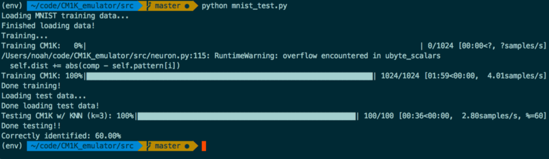
Results
— it turns out I could get pretty good results after all! My best overall (not pictured here) was an accuracy of 89% testing on 100 samples with k=5.
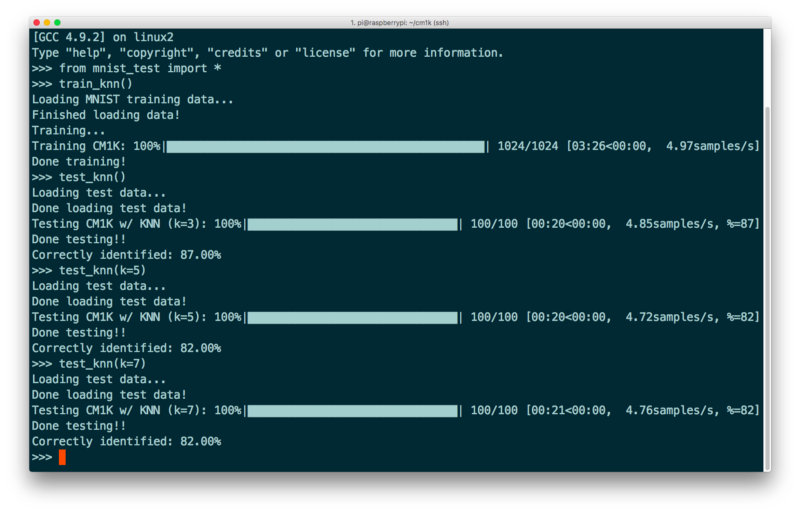 Results! Sexy progress bar courtesy of tqdm.
This level of accuracy made me pretty happy. Not quite state-of-the-art according to Yann Le-Cun’s website, but a solid B+ (A- if you round up). However, what was somewhat frustrating for me was how slow the script was, especially considering that one of the big promises of using this neural net hardware was that it would be relatively fast. However, it trained and tested at less than 5 samples/second, which I found a bit disappointing.
I was able to remedy this a little bit by changing the I2C clock speed on the Pi to 400kbps, the theoretical limit of the CM1K. This gave me slightly better results, bumping speeds up to around 7 samples/second across the board.
Conclusion
Running a KNN on the CM1K, I was able to successfully classify 100 randomly chosen images from the MNIST dataset with 89% accuracy, achieving testing and training speeds of about 7 samples/second. This doesn’t seem too bad, but an important question to ask is whether or not this is actually better than just running a KNN algorithm on the Raspberry Pi itself in software.
The closest I came to answering this question was by running a modified version of my own code on a CM1K emulator I found on GitHub. Given that emulating the CM1K is obviously not the fastest way to implement a KNN algorithm on the Raspberry Pi, this test doesn’t really demonstrate all that much. However, I was curious to compare performance.
As you can see, accuracy and speed suffers when compared to running my code on the actual chip. This is a bit strange, although pretty heartening to see, in some ways. However, I would take this with a grain of salt since I couldn’t really expect much of the emulator code.
My hunch is that a software KNN would have better performance than the CM1K if implemented in nicely written C code, for example. That being said, there are many ways I could have optimized using the CM1K as well. I believe this is true especially given that the CM1K theoretically, as calculated by the clock speed and cycle counts given in the data sheet, should be able to load a whole vector in around 10 microseconds. Running at this theoretical max, it should be able to train 1000 samples/second, meaning that there is a lot of overhead in my current method.
Optimization ideas include:
- Rewrite the code in C, to eliminate overhead in Python interpretation
- Use the parallel data bus on the CM1K instead of I2C, which may involve some hardware redesign (possibly use of a shift register) given the limits of the Raspberry Pi GPIO
Even if the CM1K could run KNN faster than the Pi could run KNN in software, the next question that comes up is whether there is a need to run machine learning algorithms offline anyways. In most applications, it seems more viable to offload this sort of computation to a server. As more and more embedded devices become connected to the Internet (it’s enough of a trend it has its own buzzword now!), embedded offline pattern recognition seems like it will become less and less useful. However, it still is something fun to play with.
I’m going to shelve this project for now to work on other stuff. However, I do have lots of ideas for how to continue going forward:
- Wire up another breakout board and daisy chain two CM1K’s together: this should allow me to get even better performance without sacrificing speed
- Perform the optimizations described above to milk more speed out of my current setup
- Experiment with the CM1K’s RBF mode (versus KNN mode)
- Write/find a decent KNN implementation for the Pi to do a side-by-side comparison with KNN on the CM1K
- Revisit using the Arduino as the master device, using an SD card module to store training data
- Develop some sort of example application using the CM1K. My top idea at this point is to develop a mobile robot that navigates based on voice commands or brainwaves
A final note is that General Vision/Cognimem’s technology is now built into the processor on the Arduino 101 chip. This may help bring their technology to the mainstream hobbyist market, although I never found many examples of people using this feature of the chip.
That’s all for now folks! It was a lot of fun to experiment with the CM1K and try and develop for a chip that is almost unknown to the broader hobbyist community. Hopefully this blog posts sheds a little light on this mysterious little guy! Feel free to get in touch with me via email if you have any comments or questions.